FIRST Tech Challenge Field “Coordinate System” Definition
Scope
This document defines the “standard” Coordinate System (orthogonal axes) definition for a FIRST Tech Challenge playing field. This definition can be used for consistent field-centric navigation, target localization and path planning.
Reference frame
The reference frame for this definition is the field perimeter wall, adjacent to the RED Alliance Station (known here as the: RED WALL). The definition is from the perspective of a person, standing outside the field, in the center of RED WALL, looking towards the center of the field.
Caveat: If the Red Alliance Station is ever adjacent to two perimeter walls, the RED WALL will be the one with most contact with the Alliance Station. If the red Alliance Station is ever adjacent to two perimeter walls EQUALLY, then the most clockwise of the two walls will be considered to be the RED WALL.
Origin
The 0,0,0 origin of the FIRST Tech Challenge coordinate system is the point in the center of the field, equidistant from all 4 perimeter walls (where the four center tiles meet). The origin point rests on the top surface of the floor mat.
X Axis
Looking at the origin from the RED WALL, the X axis extends through the origin point and runs to the right and left, parallel with the RED WALL. The X axis values increase to the right.
Y Axis
Looking at the origin from the RED WALL, the Y axis extends through the origin point and runs out and in, perpendicular to the RED WALL. Increasing Y values run out (away) from the RED WALL.
Z Axis
Looking at the origin from the RED WALL, the Z axis extends through the origin point and runs up and down in a vertical line. Increasing Z values extend upwards.
Rotation about Axes
When considering rotations about an axis, consider yourself looking down the (positive) axis of rotation from the positive towards the origin. Positive rotations are then CCW, and negative rotations CW.
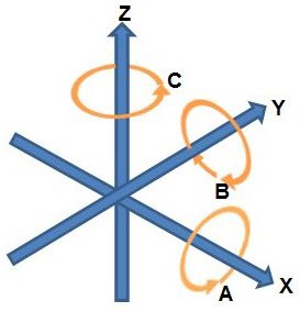
Figure 1: Coordinate Axes
An example: consider looking down the positive Z axis towards the origin. This would be like standing in the middle of the field, looking down. A positive rotation about Z (i.e. a rotation parallel to the X-Y plane) is then CCW, as one would normally expect from the usual classic 2D geometry.
Examples
Below are two examples illustrating this Axes definition.
Note
Note that in both cases the Red Alliance members are facing out, along the positive Y axis.
However, in the “Diamond” field configuration, the X axis is pointing towards the Blue Alliance, but in the “Square” field configuration the Y axis is pointing towards the Blue Alliance.
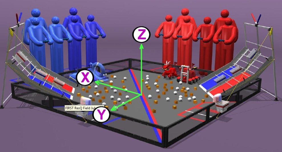
Figure 2: FIRST Tech Challenge RES-Q game field orientation
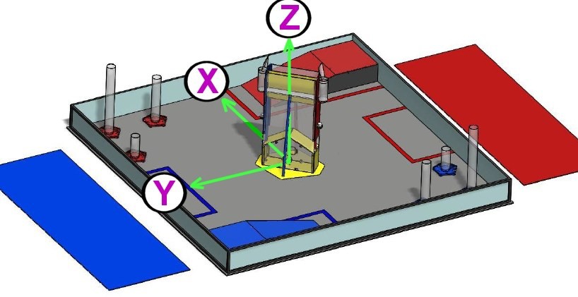
Figure 3: FIRST Tech Challenge Cascade Effect game field orientation
Measured Values
The following values have been measured from a 2016 competition field. They are representative only, and should not be assumed to be exact, or guaranteed.
Distance between opposite inside faces of panels: 3580 mm (if field assembled well: the straps give some adjustment tolerance)
Polycarbonate transparencies have a visible opening height of 255 mm
The top edge of transparencies is 30 mm from the top of the perimeter
Total perimeter height is 313 mm
Tiles are 13mm thick
So, for a diamond field configuration, the corner of the field closest to the audience, at a height equal to the top of the perimeter wall, would have a coordinate position of: (-1790, 1790, 300).